
Whether it’s materials processing, laser surgery, or remote sensing, despite the vast diversity of laser systems, they all share certain key parameters. Establishing a unified terminology and parameter system would reduce ambiguity and allow users to more clearly and accurately match laser equipment to their specific application needs when selecting and configuring it.
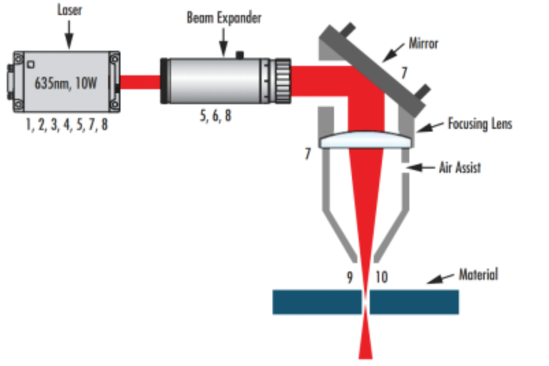
Schematic diagram of a common laser material processing system, where the 10 key parameters of the laser system are represented by corresponding numbers
The following basic parameters are the basis for understanding laser systems and are also the prerequisite for mastering more complex concepts.
1. Wavelength (common units: nm to um)
Wavelength reflects the spatial frequency characteristics of the light waves emitted by a laser. Different applications have different wavelength requirements. In materials processing, materials have varying absorption rates for specific wavelengths, affecting processing results. In remote sensing applications, the atmosphere absorbs and interferes with different wavelengths differently. In medical applications, different skin tones also absorb laser light differently depending on wavelength. Shorter-wavelength lasers and laser optics offer advantages in creating small, precise features due to their smaller focused spot size and minimal peripheral heating.However, they are generally more expensive and more susceptible to damage than longer-wavelength lasers.
2.Power and energy (common units: W or J)
Laser power is typically measured in watts (W), used to measure the output of a continuous laser or the average power of a pulsed laser. For pulsed lasers, the energy per pulse is directly proportional to the average power and inversely proportional to the repetition rate, as shown in the figure below. Its unit is joules (J).
Pulse energy = average power repetition rate Pulse energy = average power repetition rate
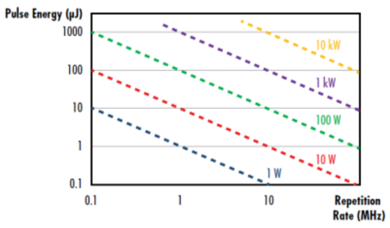
Relationship between pulse energy, repetition rate and average power of pulsed laser
Higher power or energy lasers generally cost more, require greater cooling, and are more difficult to maintain good beam quality.
3. Pulse duration (usually in fs or ms)
Laser pulse duration, also known as pulse width, is generally defined as the time it takes for the laser power to reach half its peak power (FWHM), as shown in the figure below. Ultrafast laser pulse widths are extremely short, typically ranging from picoseconds (10⁻¹² seconds) to attoseconds (10⁻¹⁸ seconds).
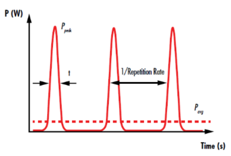
The pulse time interval of a pulsed laser is the inverse of the repetition rate
4. Repetition rate (common units Hz to MHz)
The repetition rate (or pulse repetition frequency) of a pulsed laser describes the number of pulses emitted per second—the inverse of the temporal spacing between pulses. As mentioned earlier, the repetition rate is inversely proportional to the pulse energy and directly proportional to the average power. While the repetition rate generally depends on the laser gain medium, in many cases it can be varied. Higher repetition rates shorten the thermal relaxation time at the laser optics surface and the resulting focused spot, resulting in faster material heating.
5. Coherence Length (units: mm to cm)
Laser light exhibits coherence, meaning that the electric field phase values at different times or locations have a fixed relationship. This is because laser light is generated through stimulated emission, unlike most other light sources. While coherence gradually weakens during propagation, the coherence length of laser light defines the distance over which its temporal coherence maintains a certain quality.
6. Polarization
Polarization defines the direction of a light wave’s electric field, which is always perpendicular to the direction of propagation. Most lasers are linearly polarized, meaning the emitted electric field always points in the same direction. Unpolarized light produces electric fields that point in many different directions. The degree of polarization is typically expressed as the ratio of the optical power in two orthogonal polarization states, such as 100:1 or 500:1.
The above six are the basic parameters of the laser system. Let’s take a look at the beam parameters.
7. Beam diameter (common units: mm to cm)
The beam diameter of a laser represents the lateral extent of the beam, or its physical size perpendicular to the direction of propagation. It is typically defined at the 1/e² width, the point where the beam intensity reaches 1/e² (≈ 13.5%) of its maximum value. At the 1/e² point, the electric field intensity drops to 1/e (≈ 37%) of its maximum value. Larger beam diameters require larger optics and larger overall systems to avoid beam clipping, leading to increased cost. However, reducing beam diameter increases power/energy density, which also has negative consequences (see the next parameter for details).
8. Power or energy density (common units W/cm2 to MW/cm2 or uJ/cm2 to J/cm2)
The beam diameter is related to the power/energy density of the laser beam, i.e., the optical power/energy per unit area. When the beam power or energy remains constant, a larger beam diameter results in a lower power/energy density. High power/energy density is usually desirable as the final output of the system (for example, in laser cutting or welding applications). However, low power/energy density is often beneficial within the system itself, as it helps prevent damage caused by the laser. It can also reduce the risk of air ionization in regions of extremely high power/energy density. For these reasons, beam expanders are commonly used to increase the beam diameter and thereby lower the internal power/energy density of the laser system. Care must be taken, however, not to expand the beam excessively, as this may cause the beam to be clipped by the system’s aperture, leading to energy loss and potential damage.
9. Beam Profile
The beam profile of a laser describes the intensity distribution across the beam’s cross section. Common beam profiles include Gaussian and flat-top beams, whose beam profiles follow Gaussian and flat-top functions, respectively, as shown in the figure below. However, no laser can produce a perfectly Gaussian or flat-top beam with a beam profile that perfectly matches the characteristic function, as a certain number of hot spots or oscillations are always present within the laser. The difference between the actual laser beam profile and the ideal beam profile is often described using various metrics, including the laser’s M2 factor.
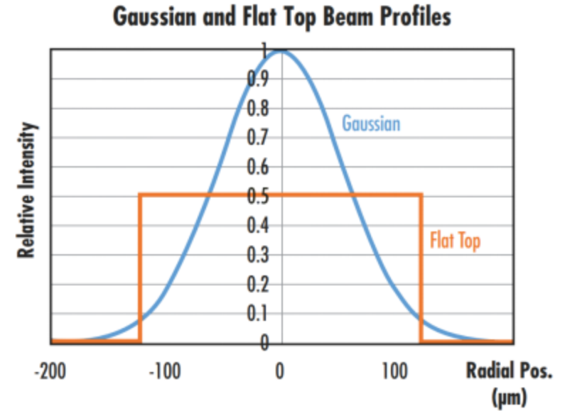
Comparing the beam profiles of a Gaussian beam and a flat-top beam with the same average power or intensity, it was found that the peak intensity of the Gaussian beam is twice that of the flat-top beam.
10. Divergence (usually measured in mrad)
Although laser beams are often considered collimated, they always exhibit some degree of divergence. Divergence describes the spread of the beam relative to the beam waist due to diffraction after long-distance propagation. Divergence becomes particularly important in long-range applications, such as lidar systems, where the target can be hundreds of meters away from the laser system. Beam divergence is typically defined by the laser’s half-angle. The divergence (θ) of a Gaussian beam is defined as λ/πw0, where λ is the laser wavelength and w0 is the laser beam waist.
After understanding the beam parameters, let’s take a look at the system parameters. The following two parameters are used to evaluate the final output performance of the laser system.
11. Spot size (usually in μm)
The spot size of a focused laser beam describes the beam diameter at the focal point of a focusing lens system. In many applications, such as materials processing and medical surgery, the goal is to minimize the spot size. This maximizes power density and enables the creation of exceptionally fine features, as shown in the figure below. Aspheric lenses are often used in place of traditional spherical lenses to reduce spherical aberration and minimize the focal spot size. Some types of laser systems do not ultimately focus the laser light into a spot; in these cases, this parameter does not apply.
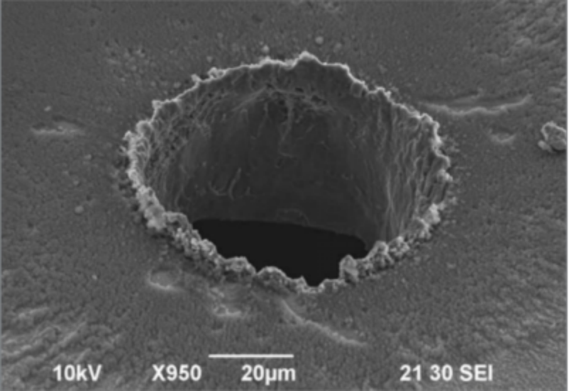
Laser micromachining experiments conducted at the Italian Institute of Technology have shown that at constant flux, the ablation efficiency of a nanosecond laser drilling system increases tenfold when the spot size is reduced from 220 microns to 9 microns.
12. Working distance (common units: um to m)
The working distance of a laser system is typically defined as the physical distance from the final optical element (usually the focusing lens) to the object or surface on which the laser light is focused. Some applications, such as medical lasers, typically minimize the working distance, while others, such as remote sensing, maximize the working distance range.
Understanding these 12 key parameters is essential for selecting, configuring, and optimizing any laser system—whether for industrial processing, medical applications, or remote sensing.
If you’d like tailored guidance on choosing the right laser system for your application, contact our team of laser experts today.

WhatsApp
Scan the QR Code to start a WhatsApp chat with us.